A hands-on guide to designing with images
For BotFactory Printers
The following guide will describe the steps needed to create and upload a circuit using an image editing tool, such as Microsoft Paint, Adobe Illustrator, GIMP or Inkscape. This guide has been written for Inkscape, but the concepts apply to any drawing tool.

Before you begin
You need the following:
- Any image editing software (Paint, Illustrator, Inkscape etc)
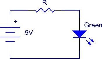
- An idea of the circuit you wish to design

Creating a New Circuit
When you launch Inkscape, a new document should automatically be created. Before you start working on yoru circuit, you need to change the canvas size to fit BotFactory's specifications.
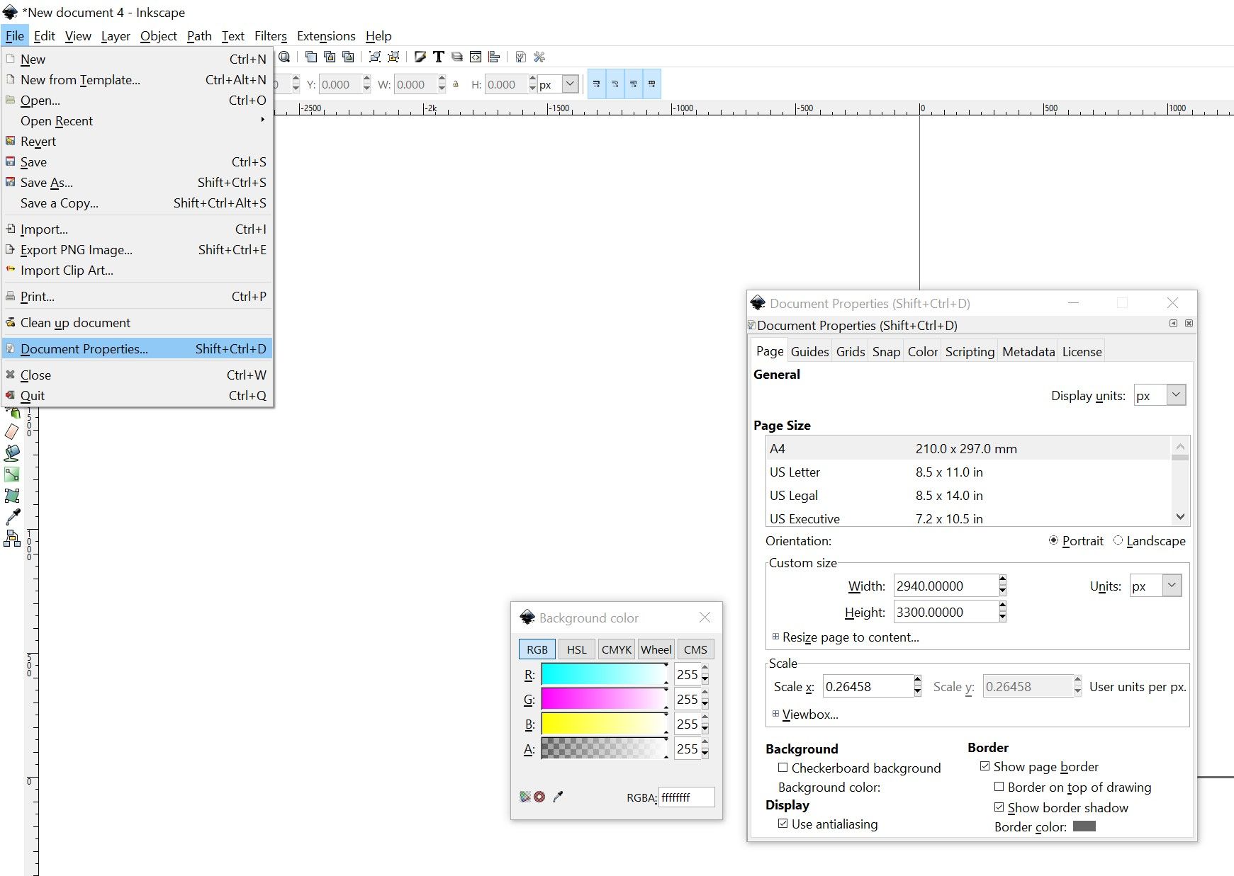
- Navigate to File > Document Properties (Keyboard Shortcut: Ctrl+Shift+D)
- In the "Page" tab, look for the box labeled "Custom Size"
- Change the width to 2940, height to 3300 and units to pixels (px)
- Click on the box next to Background color, and in the Background color window that pops up, drag the opacity (last row) all the way to the right. Alternatively, enter 255 in the last field
The updated canvas is maximum size your circuit can be in order to be printed by a BotFactory printer. If your circuit cannot fit into the canvas, the printer will generate an erorr message when you try to upload the file.
The circuit trace layout
Drawing the orientation and position of all the components in your circuit
Working on different layers
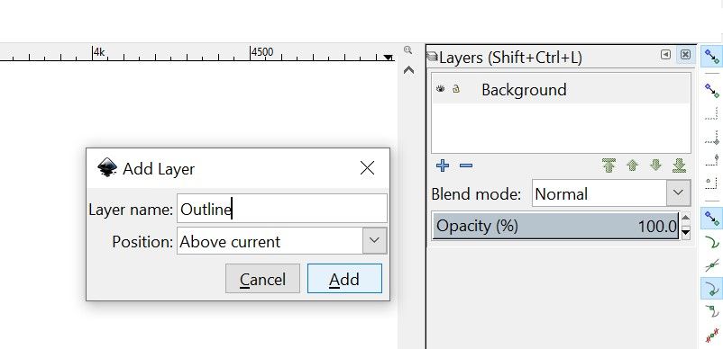
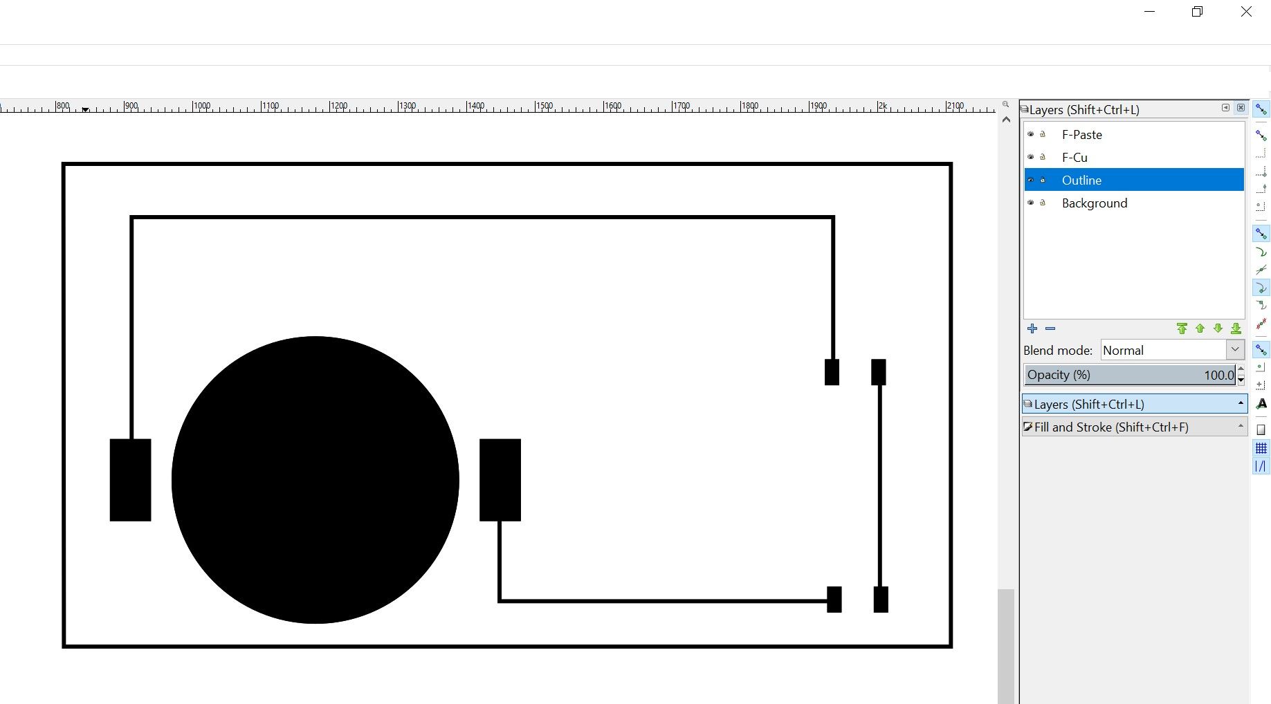
Inkscape supports working on different layers, and this is helpful when you are working with complicated circuits that involves multiple layers and/or a lot of parts. To open or close the layers panel on the side bar, use the keyboard shortcut Ctrl+Shift+L.
- Open the layers panel
- Double click on Layer 1, and rename it to "background"
- Click on the plus sign, or use Ctrl+Shift+N to create a new layer. Name this new layer Outline, and set the position to "Above current"
- Using the same method, create a layer named "F-Cu"
- Left click on the F-Cu layer to make it active
Understanding dimensions in pixels
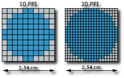
BotFactory's printers operate at 600dpi, or dots per inch. This means that there are 600 dots/pixels per 1 inch of trace you wish to print. Due to differences in resolution scaling in different image editing software, it is best to work direclty in pixels. This ensures maximum compatibility when you upload your file to the printer.
Quick conversion guide
1 inch = 600 pixels
1 mm = 1/25.4 inches = 23.62 pixels
1 mil = 0.001in = 0.6 pixels
10 mil = 0.01in = 6 pixels
1 inch = 600 pixels
1 mm = 1/25.4 inches = 23.62 pixels
1 mil = 0.001in = 0.6 pixels
10 mil = 0.01in = 6 pixels
Understanding solder pads
BotFactory's printers support printing and placing Surface-Mount Devices (SMDs). These SMDs are connected to the circuit using solder pads, which are conductive pads that are interconnected via traces.
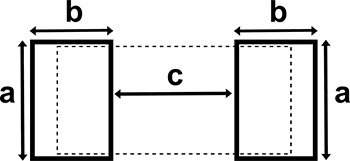
There are different types of pad arrangements (known as footprints or landing patterns). The simpler pad arrangement are those corresponding to 2-leaded components. These 2-pad arrangement use 3 parameters that define a set of solder pads: Length(a), Width(b) and Gap(c).
Quick Reference Table for typical SMD sizes
| Size (Imperial) | Length (a) (px) | Width (b) (px) | Gap (c) (px) |
| 0201 | 7 | 7 | 7 |
| 0402 | 14 | 12 | 12 |
| 0603 | 21 | 14 | 21 |
| 0805 | 31 | 17 | 28 |
| 1206 | 38 | 21 | 47 |
| 1218 | 114 | 21 | 47 |
| 2010 | 66 | 35 | 47 |
| 2512 | 84 | 38 | 90 |
If your component is not listed, refer to the data sheet for the recommended solder pad sizes and convert them to pixels
Drawing odd shaped parts
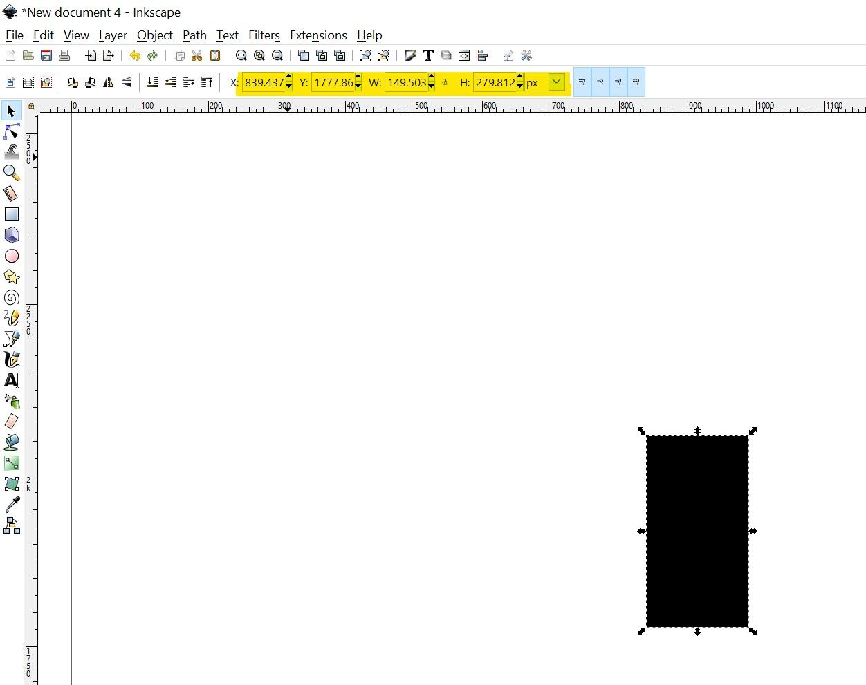
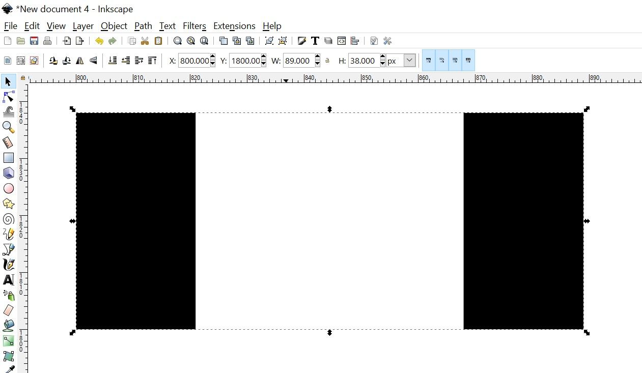
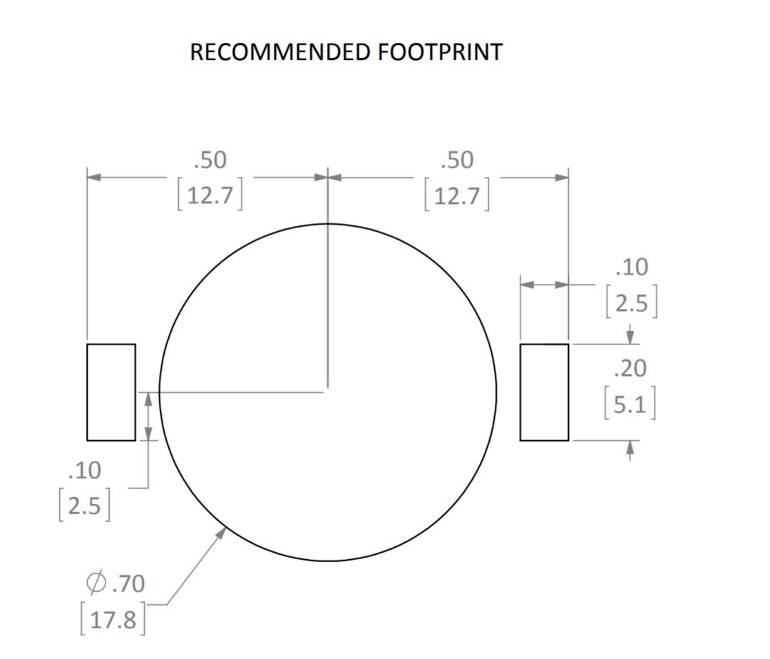
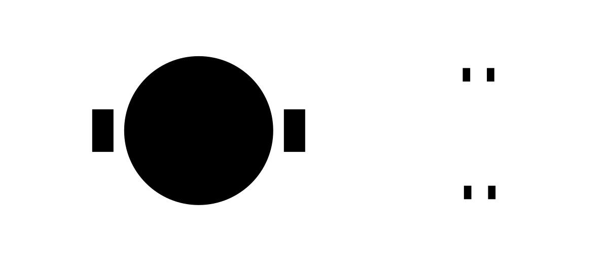
Now that we have some 1206 solder pads, we need to draw the solder pads for the battery holder. The recommended footprint can be found in the datasheet, and it is also shown on the right.
We are going to translate this footprint to graphical shapes in pixels.
- Change the numbers in inches to pixels
- Draw 2 rectangles of size 60x120px
- Draw a circle of radius 210px
- Rearrange the parts to match the spacing specified in the datasheet.
Creating the paste layer
Before routing your tracks, we need to create the layer for the printer to extrude epoxy onto.
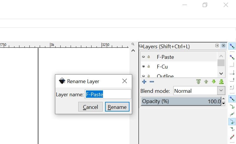
- Open the layers panel
- Right click on F-Cu layer, and select Duplicate current layer
- Rename the new layer to F-Paste
Routing the tracks
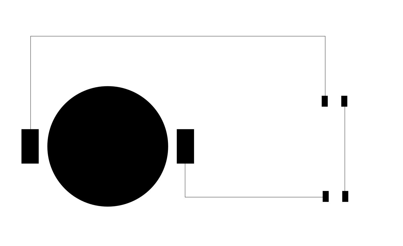
Now we are ready to route the tracks on your circuit.
- Select F-Cu layer to make it active
- Select the "Draw Beizier curves and straight lines" tool (keyboard shortcute: F6)
- Route the tracks according to your design
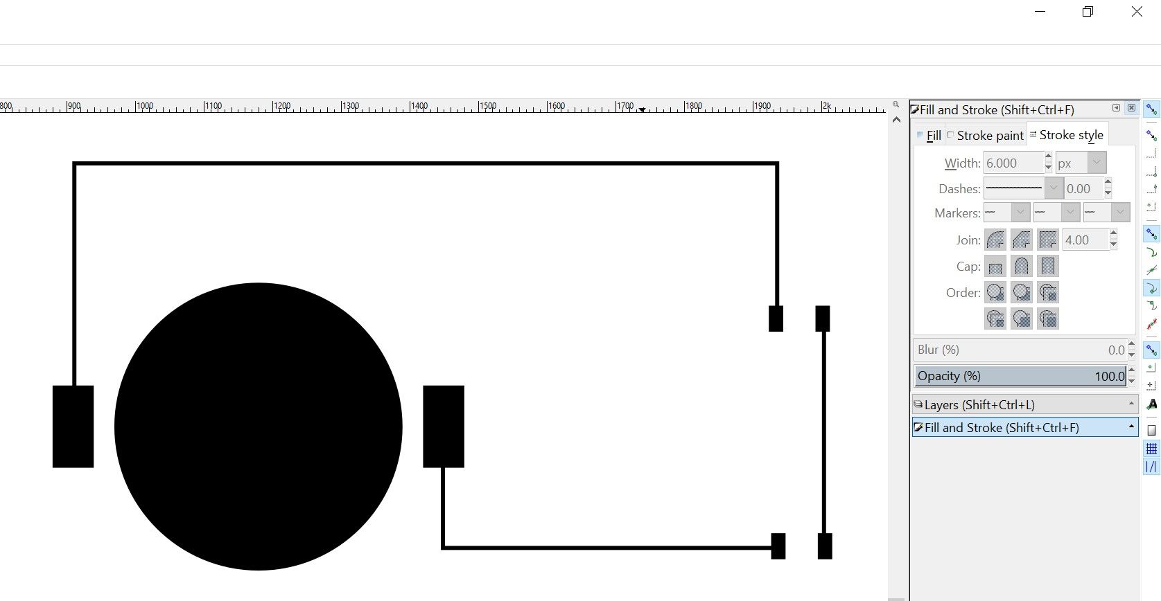
- Double click on a track, and open the Fill and Stroke panel (keyboard shortcut: Ctrl+Shift+F)
- For a trace width of 10 mils, change the width to 6 pixels
Design Rules:
| | Min Clearance | Min Track Width | Min Via Diameter | Min Via Drill |
| Squink | 12mil | 10mil | 40mil | 30mil |
| SV2 | 10mil | 8mil | 30mil | 20mil |
Creating an outline
Next, create an outline so the printer can recognize where your circuit is at.
- Open the layers panel
- Click on the Outline layer previously created to make it the active layer
- Using the straight line tool, draw a border enclosing your circuit
Creating Pick and Place files
This is the file used by BotFactory's printer to place your components
Creating the file
- Open Excel, or any other software capable of creating and editting a csv file (even notepad works)
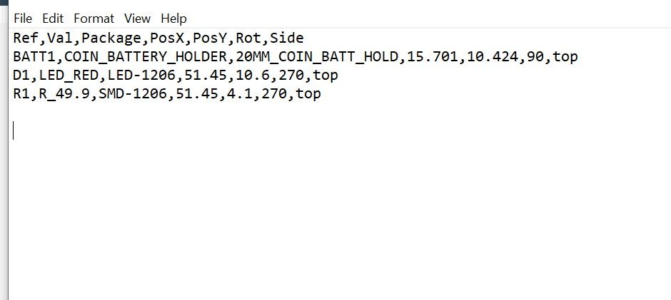
- In the header row, input "Ref,Val,Package,PosX,PosY,Rot,Side"
- Select the outline in Inkscape, and make a note of the X and Y position. In this example, it is (800,1200)
- Select the battery holder, and make a note of the X and Y position, as well as the width and height. We need to look for the center of the part, and find the distance from the origin to the part.
- The X coordinate of the center of the battery holder will be [X position (870.894) + Width*0.5 (600*0.5)] = 1170.894
- The Y coordinate of the center of the battery holder will be [Y position (1236.23) + Height*0.5 (420*0.5)] = 1446.23
- The distance between the origin and the center of the battery holder will be [(X_Part - X_Origin),(Y_Part - Y_Origin)] = [370.894, 246.23]
- This is in pixels, we need to convert it to mm. Refer to the conversion guide near the top of this document.
- The final PosX and PosY of the battery holder is 15.701mm and 10.424mm.
- If the part is rotated 90 degrees, change the Rot to 90
- Repeat this process for all other parts
- Save the file as <Project Name>-PNP.csv
Generating Files for the printer
This is the file used by BotFactory's printer to print and paste your circuit
File Exporting
- In Inkscape, open the Layers panel
- Select the Outline layer
- Right click on the layer, and select Show/Hide other layers
- You should only see the outline at this point
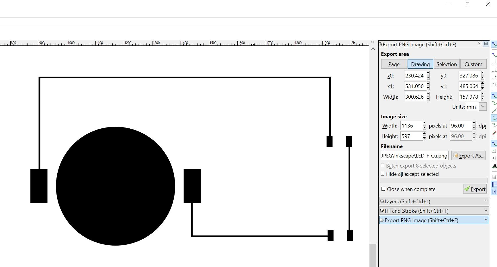
- Open the Export panel (keyboard shortcut: Ctrl+Shift+E)
- Select "Drawing" under export area
- Name the file <Project Name>-Edge.png
- Click Export
- Select the F-Cu layer, and hide all other layers
- Export the F-Cu layer and name it <Project Name>-F-Cu.png
- Select the F-Paste layer, and hide all other layers
- Export the F-Paste layer and name it <Project Name>-F-Paste.png
Final Check
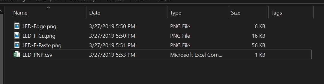
Navigate to the output folder you previously selected, and verify that you have these files in the folder.
<Project Name>-PNP.csv
<Project Name>-Edge.png
<Project Name>-F.Cu.png
<Project Name>-F.Paste.png
<Project Name>-Edge.png
<Project Name>-F.Cu.png
<Project Name>-F.Paste.png
Uploading files to printer
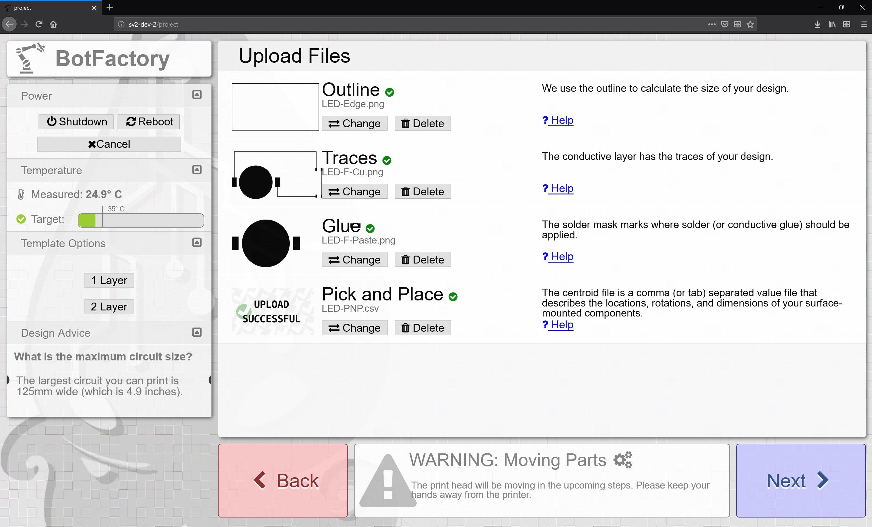
Navigate to the printer's URL, and select Single Layer print. Upload the files in the following order:
| Layer | File |
| Outline | Edge.Cuts.png |
| Traces | F.Cu.png |
| Glue | F.Paste.png |
| Pick and Place | PNP.csv |