President's Day was this Monday, and how exactly do you celebrate a President? Print PCBs using a quarter as a substrate, of course.
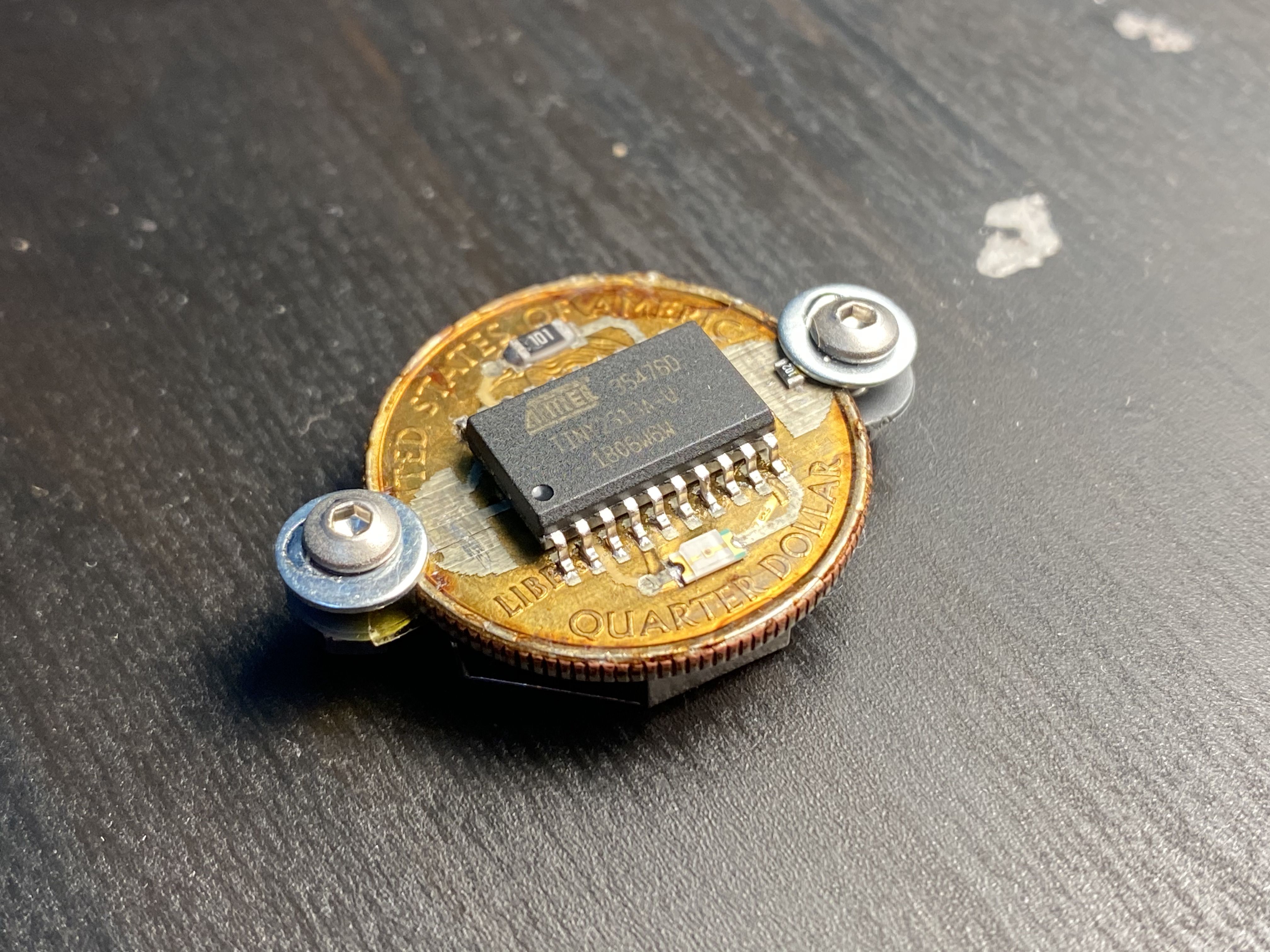
The venerable Atmel ATTINY2313a was employed for this build, and it fit quite nicely. Personally I like FDR more, but we didn't have any ATTINY85s. Lincoln would have been the most appropriate President as he is the only President with a patent, and copper is the most efficient thermal and electrical conductor. However, the 25-cent piece had the most real estate which would make PCB layout a more comfortable experience.
As with any metal-core PCB, you need to have an insulating layer over the surface. We used our SV2 Insulating ink to print 5 passes over the surface of the quarter, leaving openings (or vias) where conductive ink could be deposited. A coin-cell battery (CR2032) fits nicely on the quarter as well, and by some luck we had battery holders that would fit over the whole design. Using the screw terminals as a means of fastening the battery to the design, we didn't need wires. On the heads (where the chip and circuitry resides), open pads on the top-layer acts as VCC connection points. The screw terminals on the battery holder don't touch the edge of the coin, but with the help of washers, touch the surface of these pads, allowing 3.3V power to flow from the positive terminal to the microcontroller.
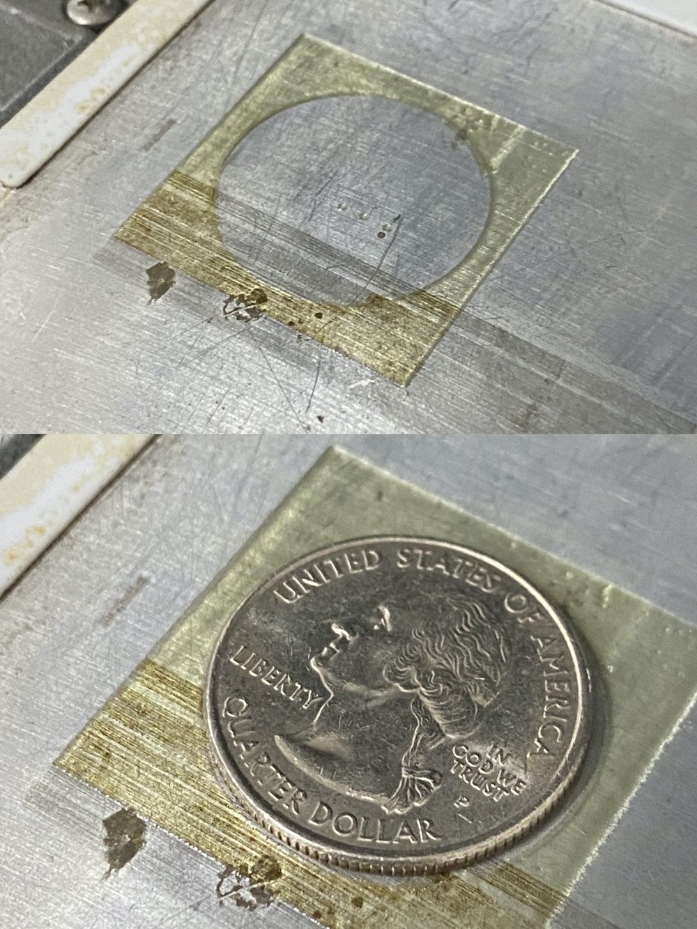
To save space, a trace was printed under the top layer, so this is technically a three-layer board (two signals on top of a 25-cent 'ground-layer'). A key consideration was aligning the coin to the machine, which was resolved by creating an outline with a single, very large via in the middle that would force the SV2 to print a quarter-sized circle for indexing and alignment purposes. Excuse the dirty surface - we print A LOT at BotFactory.
After alignment, printing took under an hour to complete. I left off a solder mask as I need to keep the VCC terminals open. That was a smart move, as the very edge of the quarter meant the washers could not make complete contact with the pads. In the end, I reflow-soldered a 0603 resistor to provide contact points for the washers to connect with the pads. The contours of a 25 cent coin is not something an EE might think about, but they nearly sunk my layout.
Assembly and pasting was done by hand in a few moments, and after applying a heat gun to the entire design, it worked right off the bat. Metal-clad PCBs are notoriously difficult to solder - extra time was applied to ensure there were no cold joints. The ATTINY2313a was programmed using a chip-clip - there was no space for headers. I did consider leaving pads on the side to program using aligator clips, but it seemed too fancy for a basic proof-of-concept.
Generally speaking, the easiest part was printing on the quarter. The hardest part was getting the battery holder to co-operate with the edges of the coin. The entire design took all of 30 minutes, and required a few adjustments after the first print failed (quarter was bigger than measured). The second print was completely fine and took under an hour. Final assembly, programming and debugging took up the rest of the afternoon. Go figures! But to our knowledge, there is no way one could fabricate this except with Inkjet Printed Electronics which is the core of our technology.
If you'd like to get the design files, or learn more about our SV2 PCB Printer, contact us and we'd be glad to help.